
Technology Behind the Light.
Explore the optical, fiber, electronic, measurement and integration technologies that form the foundation of Maxer Photonics systems.
Broadband Optical Sources
Stable. Wide. Precise.
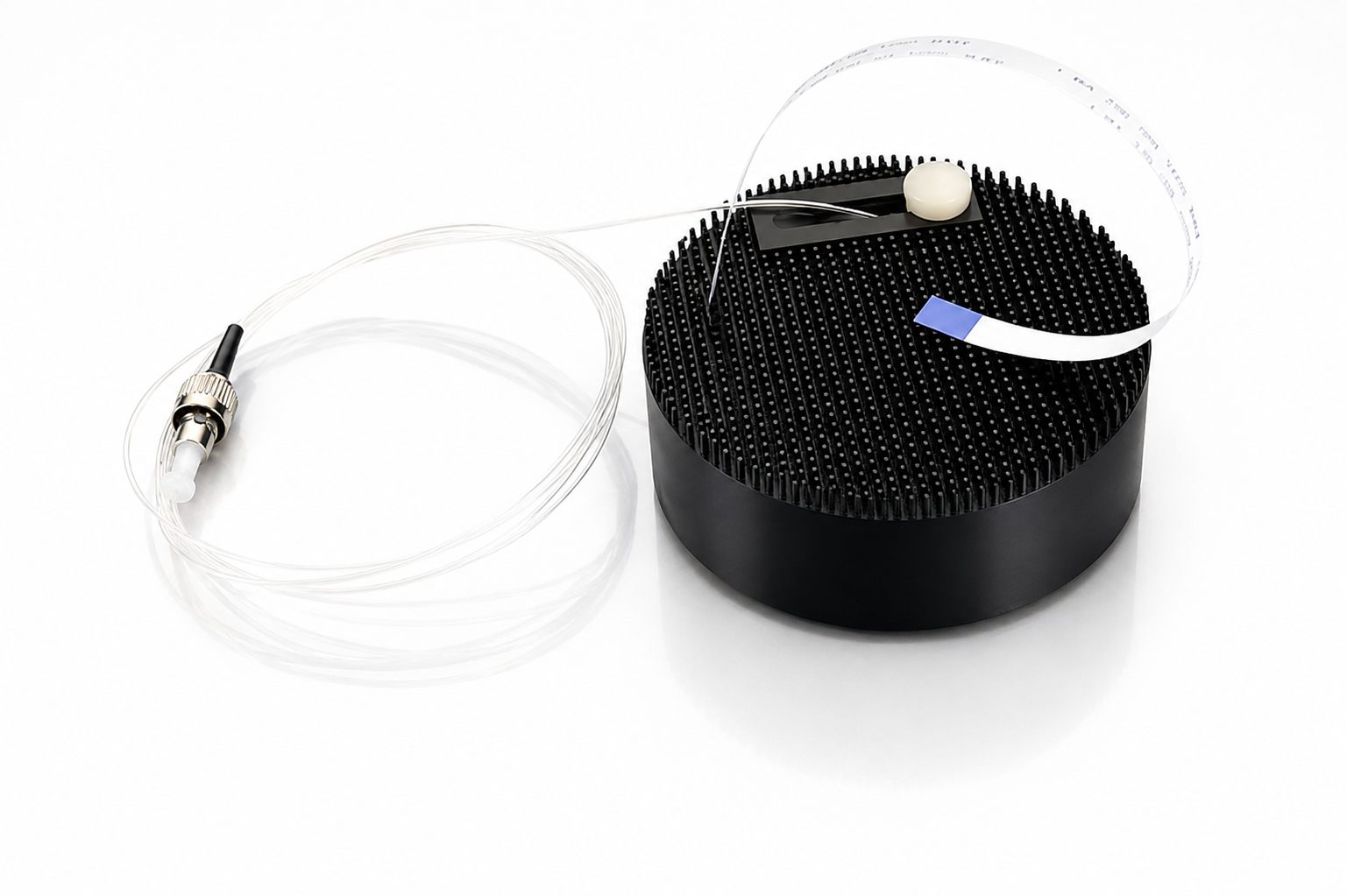
Broadband optical sources are a foundation of modern photonic systems. Maxer Photonics develops SLED-based sources designed to provide broad spectral coverage, low coherence noise and stable optical performance for demanding measurement, sensing and imaging applications.
Achieving this requires more than the emitter alone — it combines optical source technology with precision electronics and thermal management to hold performance steady as operating conditions change.
- Broad spectral coverage
- Low coherence noise
- Stable optical output
- Precision current control
- Thermal stabilization
- Long-term operating stability
- Reliable optical performance
Fiber Optic Sensing
Turning light into information.
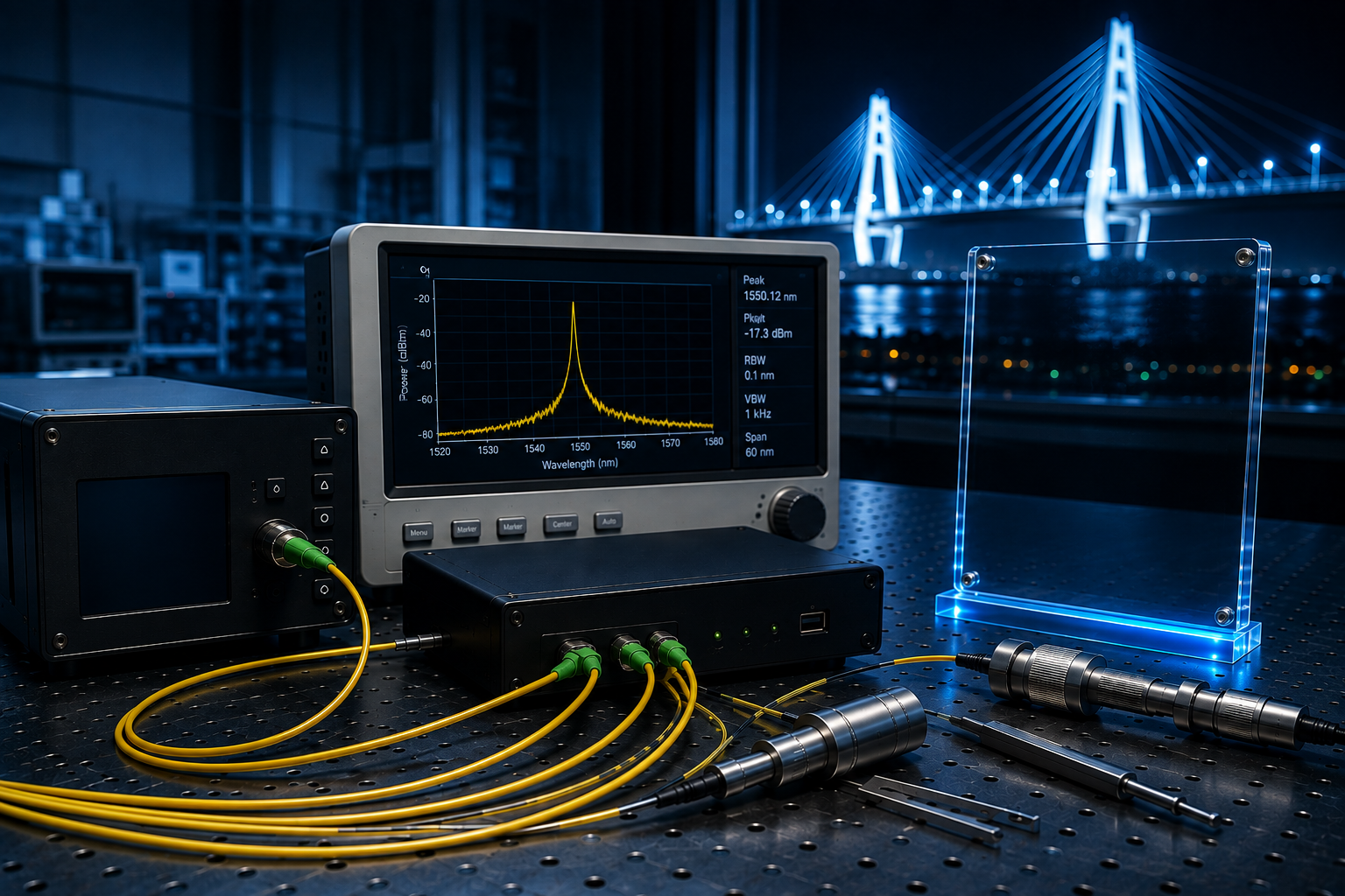
Fiber optic sensing uses light itself as the measurement mechanism. A light signal travels through an optical fiber into a defined sensing region, where a physical change in the surrounding environment interacts with the guided light and modifies its optical response.
That modified signal travels back through the fiber to a detector, where it is captured and interpreted as measurement information — turning an ordinary optical fiber into a distributed or localized sensor.
Thermal changes shift the fiber's optical response, enabling temperature monitoring along the sensing region.
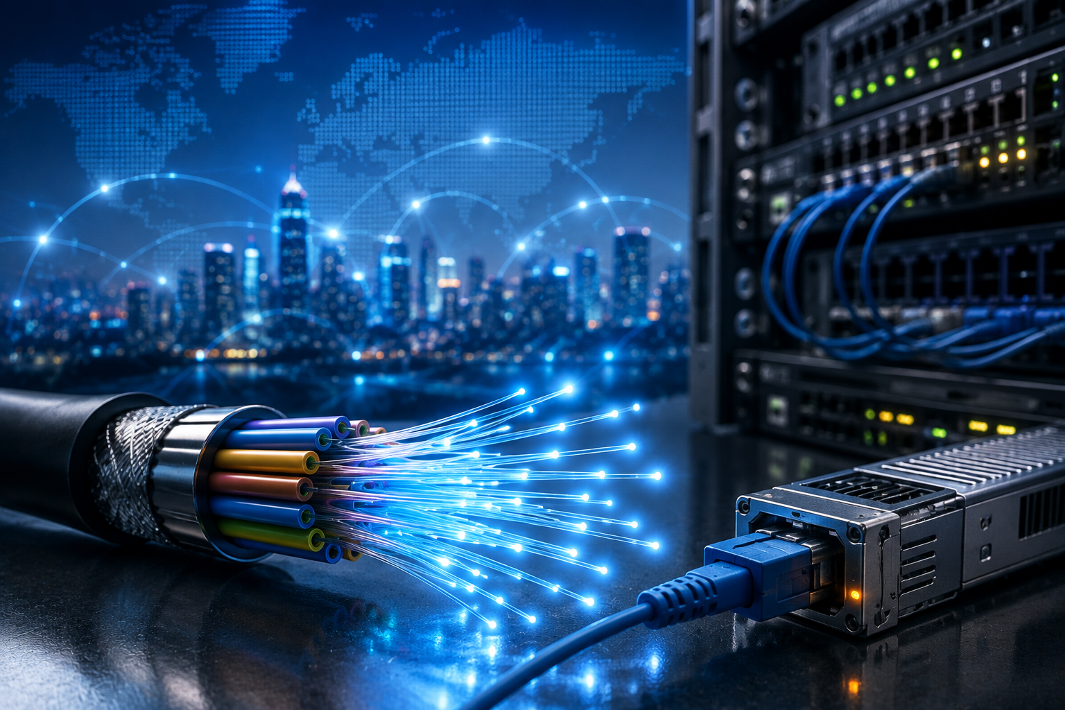
Optical communication converts electrical information into an optical signal, carries it through an optical fiber, and converts it back into usable information at the receiving end — the physical layer behind modern high-speed networks.
High Speed
Data moves as light, enabling transmission rates far beyond electrical signaling.
Low Loss
Guided light retains its strength over long fiber runs, preserving signal integrity.
Long Distance
Optical links extend communication far beyond the practical limits of copper cabling.
Multi-Channel
Multiple optical channels share a single fiber, multiplying its carrying capacity.
Fiber Optic Components & Connectivity
Reliable optical systems depend on fiber coupling, optical interfaces, fiber alignment, passive optical components, polarization management, signal routing, attenuation, splitting, isolation and dependable optical connections — the physical infrastructure that connects sources, sensors, measurement systems and photonic modules into one working system.
Fiber couplers split or combine optical signals within a single fiber path, available in coupling ratios suited to monitoring or distribution, with low insertion loss and high extinction ratio in polarization-maintaining versions.
Precision Electronics & Embedded Control
Controlling the electronics behind the light.
An optical source, its sensors, control algorithms, thermal management and feedback electronics all have to work together for optical output to stay consistent. The electronics are largely invisible, but the system's stability depends on them as much as on the optics itself.
Low-noise electronic design, precision current control and continuous feedback are what keep a photonic system's output where it should be, cycle after cycle.
- Low-noise electronic design
- Precision current control
- Temperature monitoring
- Thermal stabilization
- Feedback control
- Embedded systems
- Signal conditioning
- Optical source control
Measure → Control → Correct → Stabilize
High Stability
Low noise & drift
Precise Measurement
High sensitivity detection
Real-Time Control
Fast response & actuation
Closed-Loop System
Reliable & repeatable
Low-Noise Electronics
Minimizing unwanted electrical disturbances so they don't show up as noise in a sensitive optical signal.
Precision Current Control
Controlled electrical drive is what lets an optical source hold a stable operating point.
Thermal Monitoring
Continuous monitoring of system conditions is the first step in catching drift before it affects performance.
Feedback Control
Measured information is only useful if it feeds back into keeping the system at its intended operating state.
Embedded Control
Embedded electronics coordinate sensing, decision-making and system behavior without external intervention.
Signal Conditioning
Optical and electrical signals need to be prepared before they can be measured or acted on reliably.
Optical Measurement & Testing
Precision characterization and measurement for photonic devices and systems.
Optical measurement is essential for understanding, validating and optimizing photonic devices and systems, in the lab during development and again on the production line. Maxer Photonics combines optical, electrical and thermal measurement approaches to characterize device performance under controlled operating conditions.
Optical Power Measurement
Precise measurement of optical output and stability.
Electrical Characterization
Evaluation of electrical behavior and operating conditions.
Thermal Characterization
Monitoring thermal behavior and stability.
Signal Analysis
Analysis of optical and electrical measurement signals.
Device Testing
Characterization and validation of photonic devices.
System Validation
Verification of system performance under defined conditions.
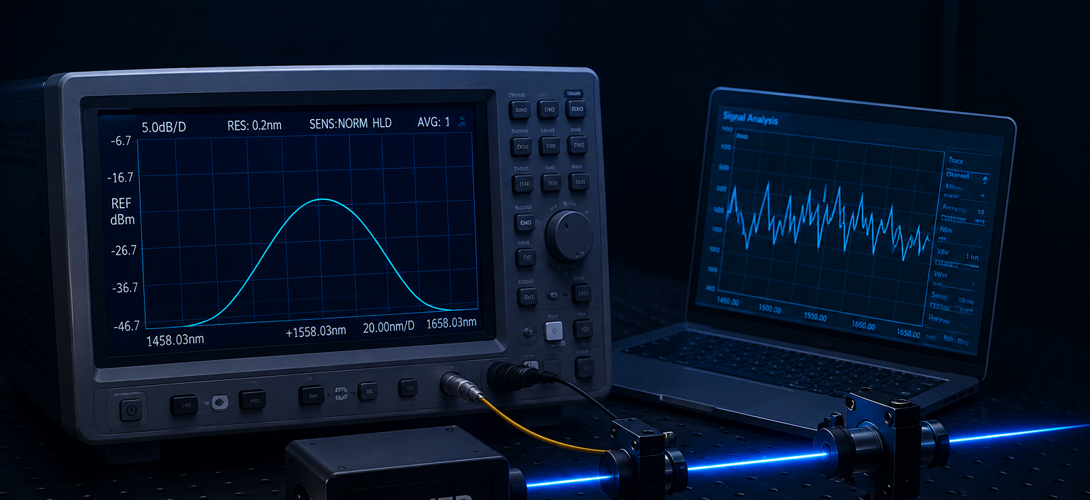
Optical power is measured directly from the device output — the most fundamental characterization step.
Optical Sensing & Advanced Measurement
Turning subtle optical changes into meaningful measurements.
An optical source launches light that interacts with its environment — through a sensing element, a measurement path or an interferometric setup. Whatever influences that interaction, whether it is temperature, strain, vibration, pressure or displacement, leaves a subtle signature in the returning optical signal.
Detecting that signature, separating it from noise and turning it into a reliable measurement is what connects optical sensing, interferometry, precision measurement and signal analysis into a single discipline.
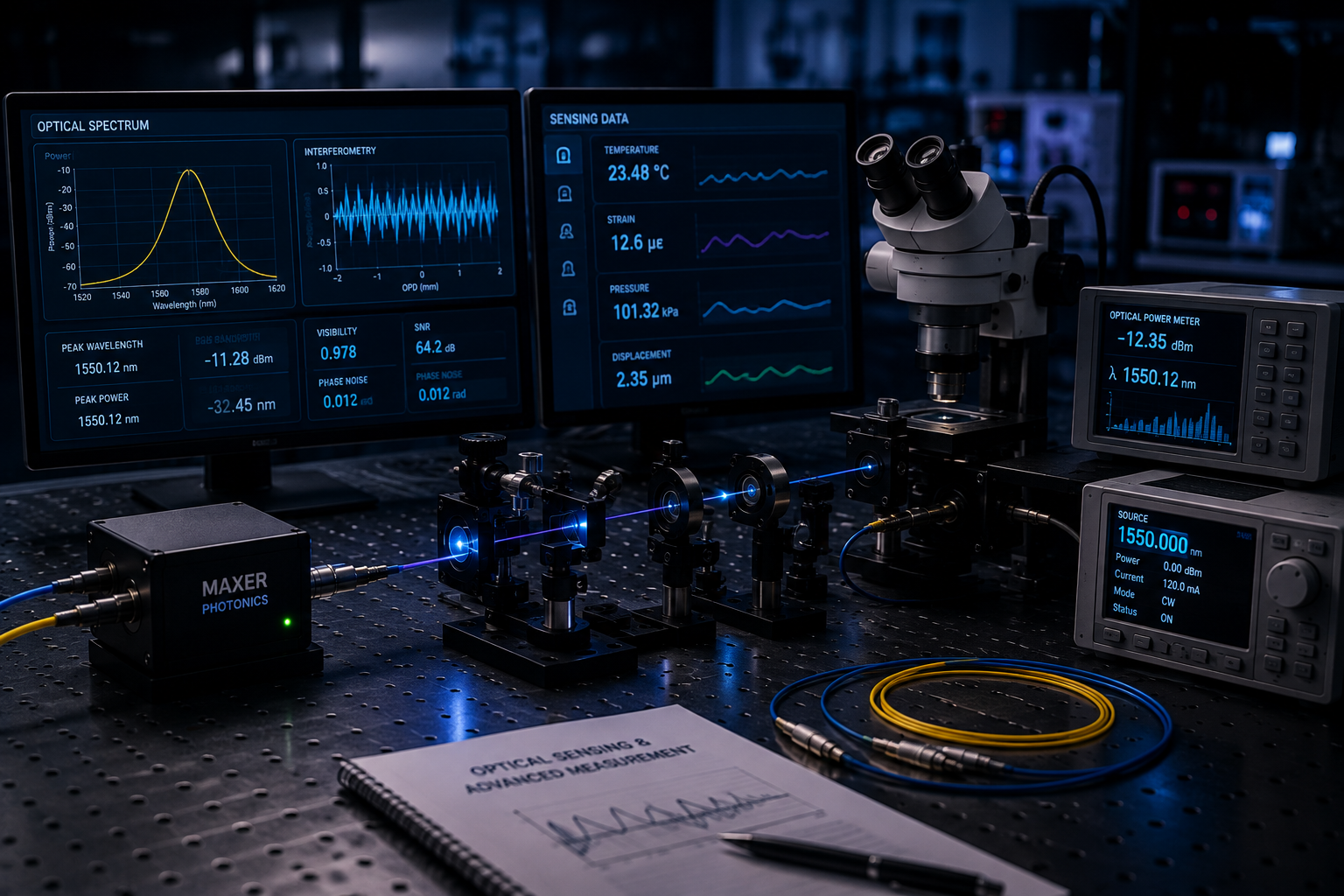
Comparing a reference optical path against a measurement path is one of the most sensitive ways to detect a subtle physical change. Where the two signals meet, they interfere — and changes in the measurement path show up as changes in that interference pattern.
Photonic Integration & System Engineering
From optical components to complete photonic systems.
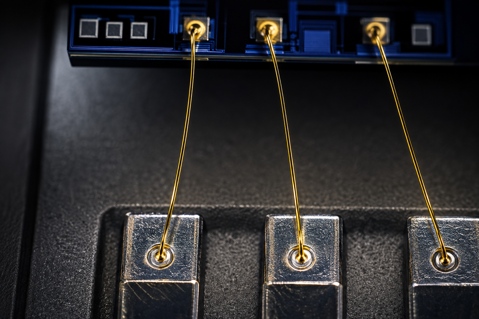
High-performance photonic products are rarely about a single optical component. Reliable systems require optical design, fiber integration, precision alignment, electronic control, thermal management, mechanical integration, optical measurement and system validation working together.
Maxer Photonics brings these disciplines together, engineering compact, stable, application-focused photonic systems rather than isolated parts.
Optical design
Fiber integration
Precision alignment
Electronic control
Thermal management
Mechanical integration
Optical measurement
System validation
Optical Layer
Defines how light is generated, shaped and guided — the starting point every other layer supports.
Fiber Layer
Couples light into and out of the system with minimal loss, connecting components into one optical path.
Electronic Layer
Drives and controls the optical source, translating electrical control signals into stable optical behavior.
Thermal Layer
Regulates temperature so optical performance stays consistent as conditions change.
Control Layer
Coordinates the electronic and thermal layers so the whole system behaves predictably.
Measurement
Confirms the assembled system performs to its design before it ships.
A finished photonic package is a stack of engineering decisions. Select a layer to see what it contributes.
Optical elements — the sources, lenses or detectors whose performance the whole package exists to protect.
Optical Alignment
Precise positioning is essential for efficient optical coupling between fiber and component.
Mechanical Stability
The package must maintain the required relationship between optical components throughout operation.
Thermal Considerations
Thermal behavior can influence both optical performance and mechanical stability over time.
Bonding & Curing
Controlled bonding processes secure an optical assembly without disturbing the alignment it depends on.
Verification
Completed assemblies must be inspected and characterized before they are trusted in the field.
“Precision optical performance depends on precision assembly.”
Engineering CAD sequence · precision instrument chassis
Manufacturing
Built under controlled conditions.
Our optical assembly, electronics and test laboratories operate under controlled conditions for cleanliness, stability and repeatable performance — in Vitoria-Gasteiz, a hub for technology and advanced industry in the Basque Country.
Research, Development & Custom Engineering
From photonic concepts to engineered solutions.
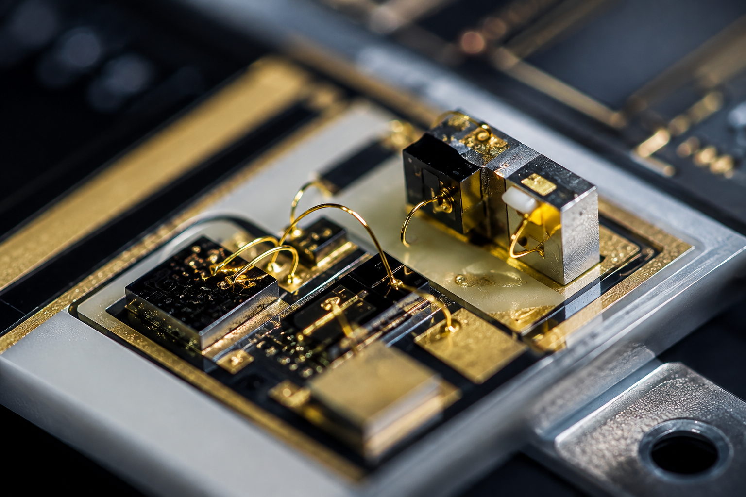
Every photonic technology on this page began the same way: as a technical requirement that had to be turned into something that actually works. That journey runs through research, concept, optical design, electronic design, prototyping, integration, characterization, validation and optimization — each stage narrowing the gap between an idea and a system that performs reliably in the field.
Complex photonic systems rarely stay inside a single discipline. Optical, electronic, fiber-optic, thermal and mechanical engineering all have to work together, which is why development is as much about coordinating disciplines as it is about any single design decision.
Concept
Optical Design
Electronic Design
Prototype
Integration
Testing
Validation
Engineered System
Photonic development begins with understanding the optical and system requirements a solution has to satisfy — not with a component datasheet. That means working through the underlying optical principles, evaluating which components and architectures could realistically meet the requirement, and validating early assumptions experimentally rather than on paper alone.
Performance evaluation runs throughout this stage, not just at the end of it — every early decision about components or architecture is tested against what the system actually needs to achieve.
A concept becomes a prototype, the prototype gets measured, and what's learned drives the next iteration — refining the design a step at a time rather than trying to get everything right on the first attempt.
Iteration 01 — an early prototype built to test the core concept, with rough edges expected.
Application-specific requirements often mean a system has to be engineered across several layers at once, all converging into one custom photonic system.
A photonic system is rarely the product of one discipline. Select a discipline to see how it connects to the others.
Optical engineering defines the light path itself — sources, optics and the behavior they need to deliver.
Photonic Quality & Reliability
Engineered for stability. Designed for confidence.
Precision isn’t a final inspection step at Maxer Photonics — it’s built into design, assembly and testing from the start. Every system is engineered for stable performance, validated for repeatability from unit to unit, and tested to confirm it holds up under real, repeated use.
Stability
Consistent output across time and operating conditions.
Repeatability
Unit-to-unit consistency verified across production.
Validation
Tested to confirm real-world, repeated-use performance.
Engineering the Future of Light.
Maxer Photonics brings together optical engineering, fiber technologies, electronics, measurement, integration and system development to transform demanding photonic requirements into engineered solutions.